K'nexion Geoscience Consulting home

Salt

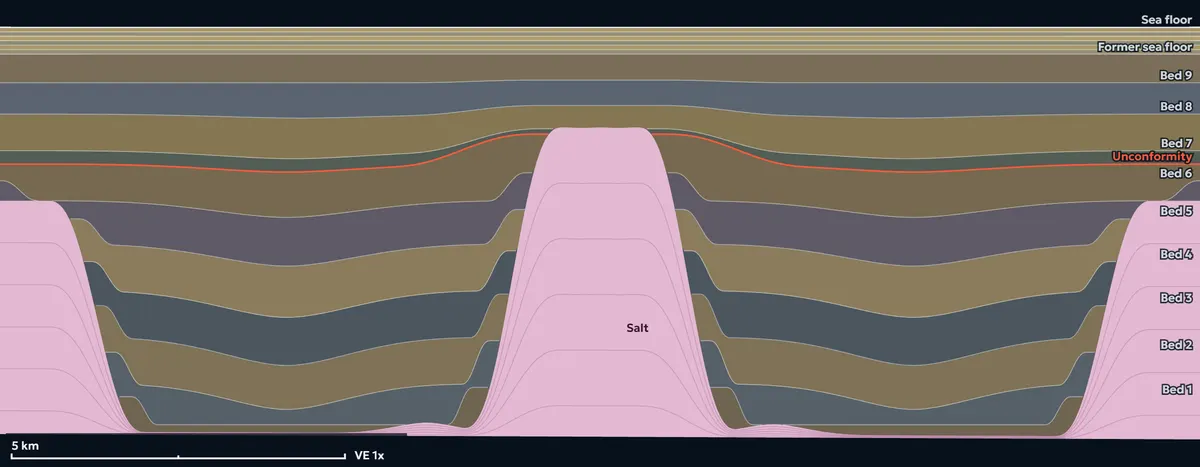
Inflate or deflate salt in a cross-section and see where the rock above bends, and where it breaks.

Salt Lab

The Salt Lab is for educational purposes only. Its simplified 2D models are not fully realistic and do not replace seismic interpretation, restoration or geomechanical modelling of any real prospect, but they are realistic enough to build intuition about multi-phase kinematic deformation of a reservoir.

Loading the section.

Tap the top of the salt to place the arrow, slide Inflate or deflate, then press Lock stage and edit again. Or start from one of the experiments under Try this.

  • Salt
  • Normal fault (throw in metres)
  • Reverse fault
  • Unconformity
  • Onlap termination
  • Mass-transport deposit
  • Slope-failure scar
  • Overturned bed (ticks point to younger beds)
  • Edit point and influence width
Model
Edit the salt
0%

Move the salt, add sediment, or both, then press Lock stage to keep it and start the next stage from the new section (up to 20). Without the box ticked the salt moves first and the sediment fills in after. Double-tap the slider to return to 0.

2.5 km
0 m
View
Faults now
FaultTypeThrow
No faults yet.

Built by Claude · Salt Lab V2

What this model obeys

  • Salt behaves as an incompressible fluid: it never faults, and its top is always one smooth curve.
  • Salt and rock always touch: no gap and no overlap along the salt contact, and no fault enters the salt.
  • Salt area changes only through your edits, as salt arriving from or leaving the section; the Rise scenario conserves it.
  • Every edit is solved for stress in the overburden: gravity, density that rises with depth, and elastic bending above the moving salt.
  • A fault forms only where the stress exceeds the rock’s Mohr-Coulomb strength. Below that, the beds just bend.
  • Faults form at about 30° to the most compressive stress: about 60° dips for normal faults, gentler dips for thrusts, which appear only where the rock is squeezed.
  • A fault grows only while the rock at its tip is above strength, and it stops at the salt top.
  • Existing faults are weaker than intact rock, so they slip again before new ones form nearby.
  • Hanging walls slide along their faults, beds keep their area within 1 %, and outside drag zones they keep their thickness measured along the shear direction.
  • A bigger edit gives at least as many faults, with at least as much throw; a zero edit changes nothing.
  • Where a salt sheet overhangs the beds beside its stem, a rising stem drags them up and rolls them under the overhang: they can pass vertical and overturn (megaflaps), with no gap or overlap at the salt and their area kept within 1 %. Ticks on an overturned bed point to the younger beds.
  • New sediment fills the lows first: it is thickest in basins, thins over highs and onlaps them, and it holds exactly the amount you deposit.
  • Sediment deposited while the salt moves pushes salt from under its thickest part toward the highs (downbuilding), and the salt area does not change.
  • No slope stands steeper than the repose angle of the bed it exposes: 5° for the youngest bed, rising with each older bed to 35°. Steeper slopes fail, leave a scar, and the same amount of sediment comes to rest in the low below as a mass-transport deposit.
  • In the sheet scenario, salt fed up the feeder advances the sheet’s nose toward the side you choose; where sediment was deposited in front, the sheet climbs over it.
  • Salt erupts only where a fault already runs from the salt to the sea floor: it rises up that fault zone as one smooth surface and spreads at the sea floor as a glacier.
  • The same preset and edits give the same section on every device, and a shared link rebuilds it exactly.

How it works

Salt flows. Over geological time rock salt behaves like a very thick fluid, so here it has no strength: its top stays one smooth curve and it fills whatever space the rock above leaves.

The rock above is brittle. Each edit is solved for stress with a finite-element model of the overburden: its weight, density that rises with depth, and the bending the salt forces on it.

Faults form only where stress beats strength. Where the stress stays below the rock's Mohr-Coulomb strength the beds just bend. Where it is exceeded, a fault starts and grows only as far as the rock keeps failing.

What is simplified

The section is 2D, the rock is elastic with an effective long-term stiffness, and blocks deform by vertical shear rather than moving as rigid pieces. Faults keep zero throw where they reach the salt, so the salt top stays smooth. The full account is in the lab's notes on the physics.

Textbook geometry rules are simplifications too: finite-element models of rising diapirs show that upturned flaps beside salt can fail in shear, and that cross-sectional area and bed lengths are not necessarily preserved. The Salt Lab relies on simple rules like these, which is exactly why it is a learning tool and not a prediction. Nikolinakou, Heidari, Hudec & Flemings (2017), AAPG Bulletin (opens in a new tab)

Try this

  • Bend before you break. On the salt wall, tap the crest and inflate to +5%: the roof bends but nothing fails. Now go to +30% and press Play: a keystone graben opens over the crest.
  • Collapse. Deflate the same crest to −30% with the arrow on its shoulder: the roof sags and collapse faults appear, dipping toward the salt.
  • Grow a turtle. In the minibasin preset, salt withdraws from under one flank and then the other, six times, each time a little more (−30%, −40%, −50%), with 150 m of sediment after each stage. The flanks sink and fill, while the thick centre of the basin is left standing high as a turtle anticline.
  • From layer to sheet. Pick Autochthonous to allochthonous and drag Rise from 0 to 100%: a pillow becomes a diapir, breaks through its faulted roof, spreads as a sheet and leaves a weld behind.
  • Roll a megaflap. Pick Diapir with overhangs and inflate the stem +20%, Lock, then again with some sediment. The steep beds beside the stem roll under the salt overhang and turn past vertical; the small ticks point to the younger beds.

Two cases from public seismic

Each case preset was built from a published, public-domain seismic profile from the deep-water Gulf of America. Load one to watch its demo history play stage by stage, then step back through the stages or keep adding your own.

Deep-rooted salt stocks and pillows

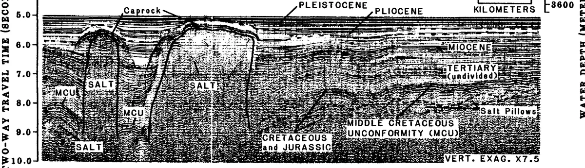
Black-and-white seismic profile: two steep-sided salt stocks with flat, caprock-topped crests rise through layered sediment from deep salt; beds turn up against their flanks, an unconformity cuts the older beds, and low salt pillows lie to the right.

Image: U.S. Geological Survey Open-File Report 81-265 (R.B. Powers, editor, 1981), part of figure 19; seismic data acquired by the University of Texas Marine Science Institute. Public domain (a work of the U.S. federal government). Cropped and resized only. Source report (opens in a new tab)

Two salt stocks rise from the deep salt source to just below the sea floor: a narrow one with a rounded top and a broad one with a flat crest, both capped by caprock. Older beds bend up against their flanks, a regional unconformity cuts across them, and the younger beds drape both crests. Low salt pillows lie to one side. The vertical scale is two-way travel time, exaggerated about 7.5 times.

How this preset was built from this image

The two stocks keep the image's order, their rough spacing and their relative widths: a narrow stock and a broad, flat-crested one, both rooted in a source about 6 km deep. The three oldest beds use the flank-upturn shape, so they climb against both stocks; an unconformity truncates them, and four younger beds thin over both crests. Two low pillows sit to the right, as in the image.

The section is drawn in depth with no vertical exaggeration, so the stocks look narrower than in the 7.5 times exaggerated image. Caprock is not a separate layer here; it shows only as the flat crest of the broad stock. The six-stage demo grows the broad stock while sediment is laid down, lets the basin downbuild under a new deposit, inflates the narrow stock, deposits again, withdraws salt between the stocks while the sag fills, and finally inflates the broad stock once more under a last deposit.

Salt-sheet front over the continental rise

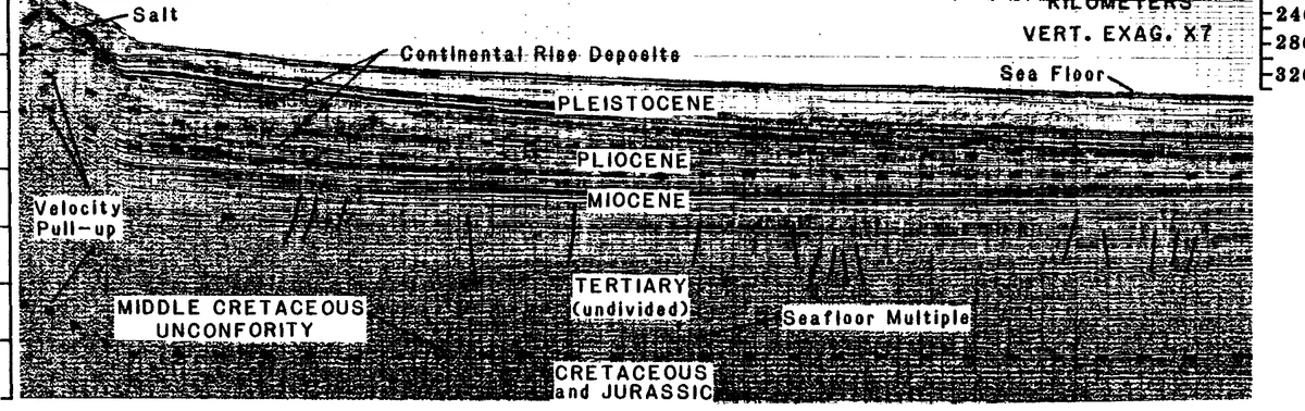
Black-and-white seismic profile: on the left, salt stands at the sea floor at the steep front of a salt sheet; to the right, a wedge of layered continental-rise deposits thins away from it above older, deeper strata and a regional unconformity.

Image: U.S. Geological Survey Open-File Report 81-265 (R.B. Powers, editor, 1981), part of figure 16; seismic data acquired by the University of Texas Marine Science Institute. Public domain (a work of the U.S. federal government). Cropped and resized only. Source report (opens in a new tab)

At the left, the front of an allochthonous salt sheet stands at the sea floor and drops steeply onto the continental rise. A wedge of younger rise deposits thickens toward the salt front and thins away from it, above older strata and a regional unconformity. The steep dark streaks under the salt are a velocity pull-up, and the deep repeat of the sea floor is a multiple: both are imaging effects, not geology. The vertical scale is exaggerated about 7 times.

How this preset was built from this image

The sheet runs off the left edge of the section, as the salt does in the image, with its front about 5.6 km in, resting on the sea floor with a steep face toward the rise; its base ramps down toward the feeder. A narrow feeder below it closes into thin source salt. Four flat-lying beds and an unconformity sit under the sheet and the rise, so the sediment in front of the sheet can build up against it.

The seven-stage demo feeds the sheet five times, each time while 100 to 120 m of sediment is laid down, with two downbuilding deposits between the feeds. The front advances over the sea floor, the rise beds onlap it, and in the end the sheet is buried under the youngest beds. Like the image, the preset is a two-dimensional cut, and the sheet's real three-dimensional shape is not known from one profile.

Why salt matters for reservoirs

  1. Salt is a slow-motion fluid.

    Over geological time, rock salt behaves less like rock and more like a very thick fluid. It moves when uneven loading from the sediments above is strong enough to overcome the strength of its cover and the drag along its edges.

    “Salt is mechanically weak and flows like a fluid, even at geologically rapid strain rates.”

    Hudec & Jackson (2007), Earth-Science Reviews (opens in a new tab); open summary (opens in a new tab)

  2. One basin, many deformation phases.

    A single salt-withdrawal minibasin can record more than 70 million years of shifting deformation: extension and faulting, then piecemeal welding, then a turtle structure, then squeezing. Each phase moved the depocentre, so reservoir sands of different ages can sit in different parts of the same basin.

    Ge et al. (2019), Basin Research (opens in a new tab)

  3. Growing salt steers the sand.

    Doctoral work on an active salt minibasin found that channels changed course when the structures around them grew quickly (about 15 m of bed-length change per million years or more), and ponded sand-rich fans built up when growth was slow (under about 10 m per million years). How fast the salt moved helps decide where the reservoir sand ended up.

    Doughty-Jones (2014), PhD thesis, Imperial College London (opens in a new tab)

  4. Timing decides connectivity.

    Sand-rich channels and lobes were first trapped in minibasins and in the hanging walls of salt-detached faults. Later they filled those basins and bypassed them downslope, and rising salt walls then cut through the earlier deep-water systems. The same sand body can be connected or chopped up, depending on when the salt moved.

    Rodriguez Rondon (2017), PhD thesis, Imperial College London (opens in a new tab)

  5. Beds bend, thin and fracture right next to a diapir.

    Next to a rising diapir, strata are dragged upward and thinned into unconformity-bound packages. “Hook” packages fold within a narrow 50–200 m zone with more than 70 degrees of angular discordance and abrupt facies changes, while “wedge” packages fold gently over 300–1,000 m. Core from a diapir flank shows fracturing tied to this drape folding.

    Giles & Rowan (2012), Geological Society Special Publications (opens in a new tab); Abu (2023), PhD thesis, Imperial College London (opens in a new tab)

  6. Faults appear only where the salt pushes hard enough.

    Kilometre-scale radial faults around a salt stock form first as the roof over the stock stretches. Later, the widening salt stem pushes on its flanks and creates or reactivates more faults. These faults control fracture patterns, fluid pathways and reservoir compartments around the diapir, and can line up stacked reservoir targets.

    Coleman, Jackson, Duffy & Nikolinakou (2018), Geology (opens in a new tab); Coleman (2018), PhD thesis, Imperial College London (opens in a new tab)

  7. A “weld” may not be sealed at all.

    When salt flows away, the rocks above and below it meet at a salt weld, but flow rarely removes all of it. Up to about 50 m of salt can be left behind, and seismic data usually can't tell a partial weld from a complete one. One PhD found that thin, broad welds offshore Brazil were likely to leak, letting fluids cross from source rocks below to reservoirs above.

    Wagner (2010), PhD dissertation, The University of Texas at Austin (opens in a new tab)

  8. Salt leaves a stress fingerprint that lasts millions of years.

    Geomechanical models show that salt loading creates pore-pressure anomalies reaching kilometres into nearby mudstones, and these can take millions of years to dissipate. As a salt layer welds, stress jumps in the sediments near the weld tip, which can compact, fracture or fault them. Both effects matter for drilling and for producing reservoirs near salt.

    Nikolinakou, Luo, Hudec & Flemings (2012), AAPG Bulletin (opens in a new tab); Heidari, Nikolinakou, Hudec & Flemings (2016), Tectonophysics (opens in a new tab)

  9. Production feels the salt too.

    In coupled flow-and-deformation simulations of a reservoir pierced by a salt dome, 13 years of production changed stress differently next to the salt than in flat-lying parts of the reservoir. Reservoir dip, salt creep and well location all changed the pressure drawdown, the stress path and how much the reservoir compacted.

    Hernandez Riveros (2018), graduate thesis, The University of Oklahoma (opens in a new tab)

  10. Under the salt, the picture itself is uncertain.

    Salt bends seismic waves, so images of reservoirs below it depend on a velocity model that is never known exactly. Velocity uncertainty translates directly into uncertainty in where subsalt structures really are, yet usually only one image is built and interpreted.

    Li, Caers & Sava (2015), The Leading Edge (opens in a new tab)

Further reading

Working a structure near salt? Talk it through with Ben.